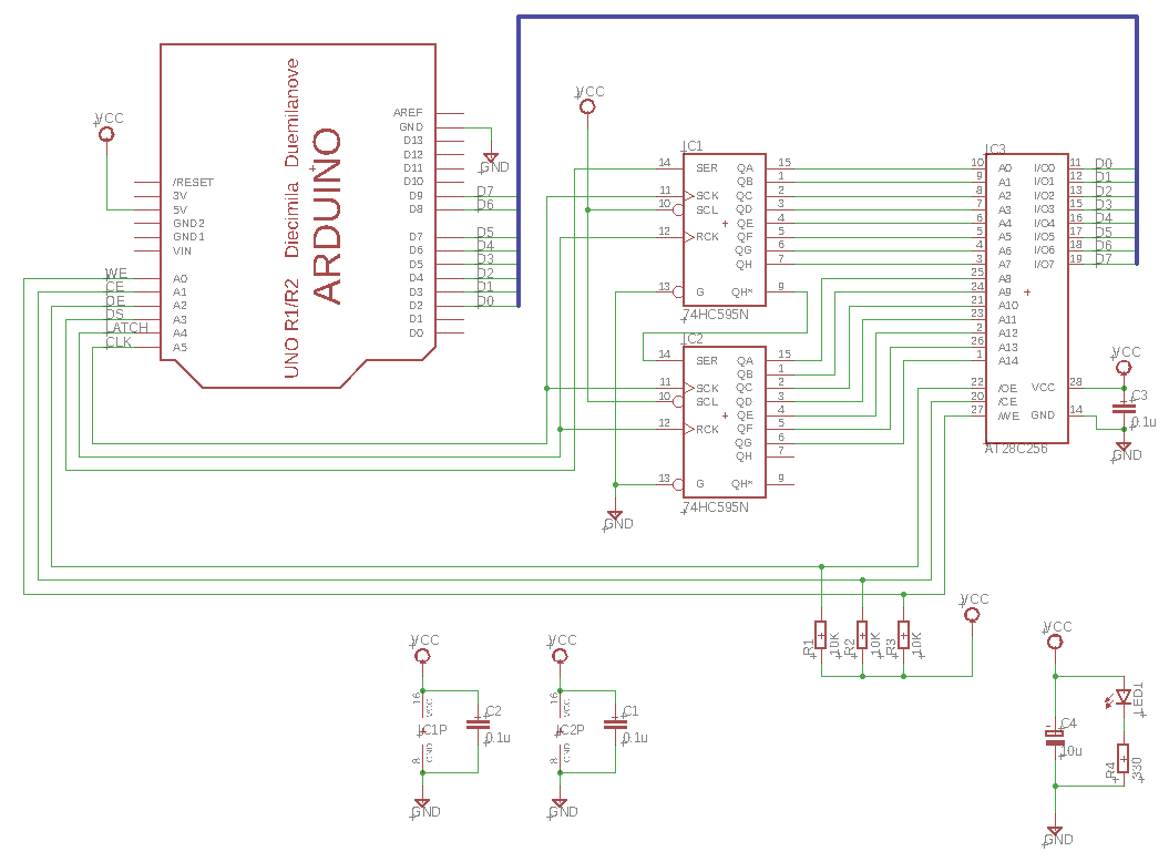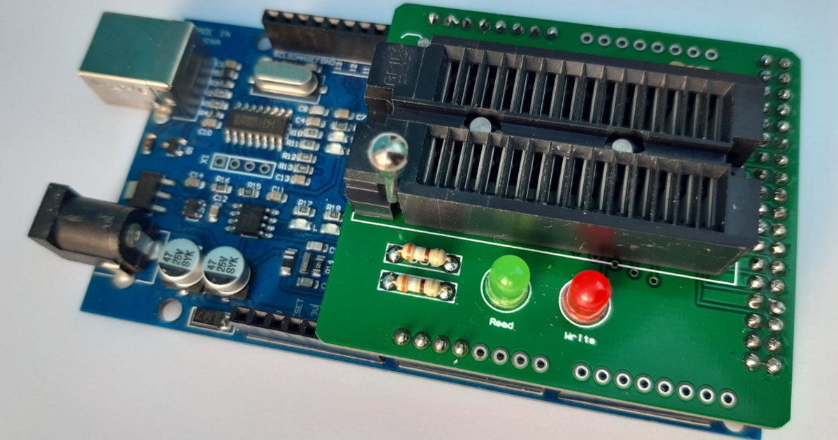

To understand this we can first look at the “Software Command Sequence” table in the data-sheet.įirstly, we can see that the commands can be up to 6 write cycles long, where a write cycle is writing a specific byte to a specific address. In order to write to the device we can not simply drive WE# low, we instead have to send a specific command sequence to the device to unlock it and then we can write our data. This is where things get slightly more complicated. We shouldn’t have to worry about these too much right now. Simple! Notice that there are lots of arrows with ‘T’ labels, these are the specific timing parameters for the different changes. This will result in the stored byte being present across DQ7 to DQ0. We can see that to read from the device we must have CE# low, OE# low, WE# high and the desired address present across A18 to A0. Reading from the flash chip is the easiest and quickest of operations, to see how it’s done we can look at the timing diagram provided in the data-sheet. However, I soon decided that it would be easier, simpler and faster to use an Arduino MEGA and connect all of the pins directly to the MEGA. This was possible by using some daisy-chained 8-bit shift registers to control the address pins and then the rest could be directly connected to the UNO. I would have to control the 30 pins on the flash chip with only 18 available pins on the UNO. Initially, I was going to use an Arduino UNO for this project, but I encountered an issue. Sometimes active low is shown by a solid line above the pin name instead of the ‘#’ after the pin name. Notice the ‘#’ after each of these pins, this means that they are active when the signal is driven low(0), for example, to enable DQ7 to DQ0 as output pins we must drive OE# low.

DQ0 – DQ7 : the data pins that will either output the 8-bits(1-byte) of data from the MSB at DQ7 and the LSB at DQ0, they also are used to input the byte of data during writing data or commands.A0 – A18 : the address pins that will be used to select the address of where to read/write a byte of data.

Here is a quick description of the function of each pin, the data-sheet also provides its own table on each pins function. This data-sheet also contains information on the other variations of this chip so make sure you are looking at the correct information. We can find all this information inside of the data-sheet. I imagine this would be compatible with most parallel flash EEPROM chips as they seem to have similar pin-outs and command sequences such as the AM29F040B, a common EEPROM used to replace the GameBoy cartridge mask ROM.įirstly we should begin by having a look at the pins available for our use and what each of them does. The EEPROM / NOR Flash I am working with is the SST39SF040, however, the process would be the same for the SST39SF010A and SST39SF020A as they are the same flash chips of different memory sizes. I will be attempting to use an Arduino to program a parallel EEPROM / NOR Flash which can then be used to replace the ROM in older games such as those for the Gameboy, NES or the SNES. I have seen many different ROM dumpers and programmers for retro game systems such as the Nintendo GameBoy, this got me wondering how I could achieve the same thing with an Arduino as most of the programmers use the same chip as the Arduino boards to interface with the cartridge.


 0 kommentar(er)
